The Cab Control Manual, By D.W. Ley was a 29 page booklet published by Kirdon Electric Ltd around 1953. Here a very mildly abridged text is reproduced along with the original hand-drawn figures to aid the passing hobbyist. It should be remembered that the text hails from an age where electronic and computerised controls such as DCC were unheard of, but the scheme outlined does provide some extra utility to DC powered layouts, at the cost of greater user input. Any notes or comments will be marked [in this manner]. The seven pages of period 1950's advertisements have been omitted.
The Cab Control Manual
by D.W. Ley
For many years Kirdon Electric have been seeking a way to present the problems of wiring and controlling model railways.
This booklet, we feel, is the answer for the uninitiated. Mr. Ley has written his booklet in a lighter vein in order that it may prove more palatable.
Published by Kirdon Electric Limited, Factory Yard, Hanwell, W7, London.
AN INTRODUCTION TO BETTER CONTROL
There is no finer hobby than that of model railways. It has progressed a great deal in the last twenty years, so much so that many enthusiasts and would-be modellers are mystified by the maze of circuit diagrams and systems of control hurled at them.
Nearly every man and boy, at some time, desires to own and run a model railway. He is not often an electrician. It is for these people that this manual is written - for the average railway modeller who does not want to wade through complex diagrams, but wants a realistic working model railway.
For price, performance, practicability and realism, cab control is the finest method of operating a layout.
I am an average railway modeller, and I have written this manual so that we may all understand it. Simplicity is our keynote, so I suggest we start at the very beginning.
D. W. LEY.
WHY CAB CONTROL IS BEST
Perhaps you are just about to buy a complete train set (electric, of course), or maybe you have one already; possibly you have constructed all your track work on a baseboard and hand-built a loco and some stock. All right, your train will, or does, run on the layout supplied or that you have formed up.
In due course track is extended, a baseboard is permanently arranged - for all model railways perform best on a permanent structure - and thoughts turn to adding another train. To run this train on your layout, along with your existing train, you should use cab control. Why should you? Well, hold on to your hat, here come a few reasons.
1. You can adapt any layout to cab control.
2. You can control several trains from one control board, without the trains affecting one another, and completely independently of each other, in any direction.
3. You can control a train throughout its journey from one controller, just as if you were driving right there in the locomotive cab. From start to finish you are the driver, watching signals and time throughout the entire run. How's that for realism?
4. No complex circuits are required.
5. You don't have to be an electrician to wire cab control.
6. As your train travels from one section to another (more about sections later) there is no jerking, no risk of shorting, in fact no controller trouble at all, as there is with other methods. With cab control you stay on the same controller throughout the journey.
7. It is cheaper than all other methods.
8. Operation is simplicity itself.
9. You can try or revert to any other method of control without any difficulty or rewiring.
10. If any locomotive is troublesome, it does not affect others being run at the same time. If a locomotive overloads its power supply and the current is cut off by the auto cut-out, all other locos and cabs keep working.
11. Cab control suits all gauges, scales and methods of current collection. Whether you are two-rail, outside or inside third rail, stud contact or overhead traction, you can have cab control.
12. Perhaps what is more important to you is that whatever equipment you have, or whatever you are going to buy, you can have cab control. So come on, all you Scale, Dublo, Farish, Trix, Märklin, Lowke, Lionel, Tri-ang and "what-have-you" fans, go cab control now.
WHAT YOU HAVE IS WHAT YOU NEED
If you are running a model railway now you have a power pack and control system of some sort. Should you be about to purchase a layout, you will need to buy one along with it. That's fine, because any power pack with control will do for cab control. Suit your pocket when buying your power unit, for the simplest, cheapest unit will do, provided the output is sufficient for the train it is going to run. With cab control you are only going to run one train from that power pack, so that is all the output you require. Accessories, lights and solenoids should be run from a separate transformer, unless the power pack has accessory outputs.
There are a considerable number of units or combinations of units which are generally in use or available. They should have a maker's name or brand, and are usually covered by a guarantee. They are all safe enough for use by anyone over the age of six months, as cut-outs or warning lights are fitted. All are suitable for cab control and some of the most popular units are listed here. All are for A.C. mains 220-250 volts.
Power Packs for Cab Control
Complete Units [1950's controller specifications have been omitted]
The Formo transformer/rectifier/controller
The Trix single transformer/controller
The Hub M/1 transformer/controller
The Hub M/2 transformer/controller
The Bassett-Lowke BL/1 transformer/rectifier/controller
The Kirdon Minor transformer/rectifier/controller
The Kirdon DC/ 1 transformer/rectifier/controller
The Lionel Trainmaster transformer/controller
The I.M.A. transformer/rectifier and Tri-ang speed control
The Hornby Dublo transformer and Hornby rectifier/controller
The Kirdon Midgi-Pak transformer/rectifier VR/2 controller
The Kirdon Midgi-Pak transformer/rectifier and S.C. controller
The Trix twin transformer and 1 or 2 Trix controllers
The Kirdon Midgi-Pak transformer/rectifier and C.7 controller .
Further combinations can, of course, be made according to your requirements or fancy.
Say you have a Tri-ang set and are running it from an I.M.A. transformer/rectifier and Tri-ang speed control, and you wish to run a second train. Your layout has been extended and you have just purchased a second locomotive. You want to run two trains quite independently of one another, and have decided upon cab control, of course. All you need is another unit or combination with an output of 12 volts D.C. at 1 amp. If you are satisfied with what you have, buy it again. If you want a change, there are plenty to choose from. You can choose for control, price, convenience or colour of box - it doesn't matter.
Now you have two power packs, two locomotives, and a layout. You are ready for cab control, but before we go into a dreamland of realistic operation a few very easy essentials should be discussed. Knowledge of, and attention to, every detail ensures success and reliability in all model railways.
SECTIONS AND SWITCHES
1. Sections.
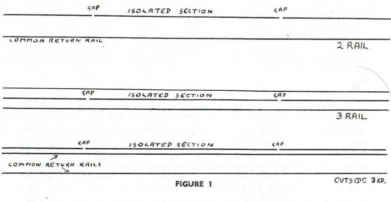
A section is an isolated stretch of trackwork. A length of track is isolated electrically from the rest of the layout by disconnecting one current-carrying rail from the source of power supply. In the case of two-rail track, one rail is cut with a fine saw in two places, for instance three feet apart, and the area of three feet is then isolated from the power supply. With three-rail track, you cut the inside or outside third rail, as the case may be. With most proprietary systems of three-rail track, an insulating tab is inserted between the third rail clips.
See Figure 1 for examples.
Sections can, of course, be made in stud contact trackwork by disconnecting a few studs from the power supply, or in overhead systems by cutting the overhead wire or catenary and joining with an insulating material. Commercially produced stud and overhead systems like Märklin have ready-made isolating equipment.
Sections should be made, if possible, on straight runs of track, for if you cut a rail on a curve the tension of the curved rail will make the cut ends stick outwards and throw the track out of gauge. This applies only if you are using two-rail traction.
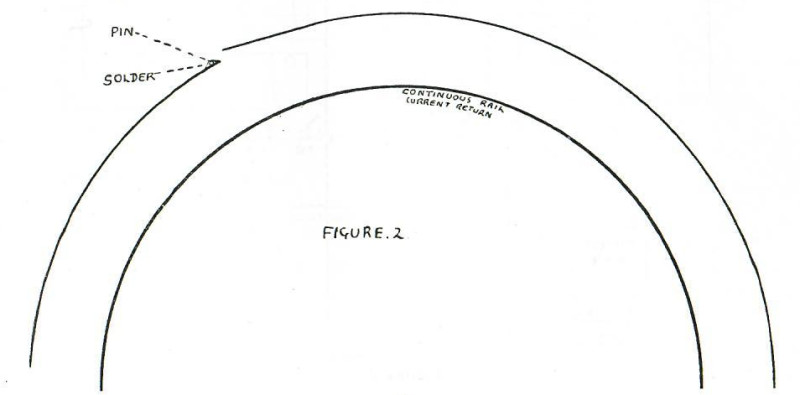
Should it be essential to make the end of a section on the curve, a neat method is to make all cuts on the outside rail and then to hold the track in a gauge (Peco, Hambling, etc.). Force a pin in alongside the rail, so that the pin stops the rail springing outwards. A handy tool for pushing pins in baseboards is the "Rampin," available at most stationers. The pin is then soldered to the rail and the top cut off and filed smooth with the rail surface. Repeat the process to the other rail end. See Figure 2.
Note. - All section cuts should be made on the same side throughout the layout, preferably on the left-hand side (from the cab) on the down line, on the right-hand side on the up line. This, of course, applies only to two-rail traction.
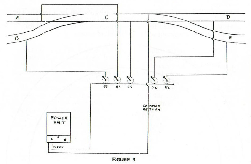
These sections are essential for any type of multi-train control. A glance at Figure 3 [below] will show you how two trains can be controlled independently from one power unit/controller. Note that there are five sections - A, B, C, D and E. These sections are controlled by five switches - AS, BS, etc. The current return is one common rail and one common wire. It is easily possible, therefore, to operate two locomotives on this stretch of track one at a time. Loco X can be parked on section D and DS switched off. Loco Y can then run anywhere on the layout excepting section D. Loco Y is then parked on section E and Loco X has the run of the trackwork.
If both the locos were allowed to run by switching on all the switches they would both do exactly the same as each other. This would be quite pointless. That is where cab control comes in.
2. Switches.
In order to run several trains we have to use sections. We know how to make them. All we have to do is to put a switch on our control panel, so that we get the section in circuit when we want it and out of circuit when we do not need it.
S.P.S.T. toggle switches are the most suitable and cheapest for the job. (Translation : single pole, single throw switch, with a lever sticking out of it working on/off.) A wire from the controller leading to a section is broken by this type of switch. For ten sections you need ten switches.
Note at this point we only have one wire broken by a switch. The current returns through the unbroken rail or rails via the bonding through a common feed to the power pack/controller cab or cabs. All joints in the circuit will be soldered, of course.
SIMPLE CONTROL
The full title of the system about to be explained is Multiple Supply Cab Control. This means that each loco has its own individual supply from its own controller power unit. For example, each Hornby loco will have its own individual 12-volt D.C. 1-amp. output unit. Each unit can be wired to the same A.C. mains plug, but, as you will appreciate, each locomotive supply will be quite separate and individual in every way. That is multiple supply.
It frankly is of no importance that you understand why the next fact is so, but for the purposes of cab control it is so, and that is that.
One wire or one rail can carry any number of positives and negatives, provided they come from different sources. In multiple supply cab control each loco has its own supply and there is no connection between its source and any other source on the same layout. I know they come off the same mains, but it does not matter, for it only applies to the output of your power pack. A transformer's output has no direct connection with its input.
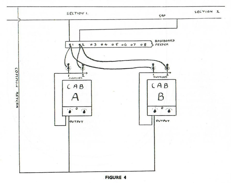
Figure 4 shows two sections of an eight-section layout wired up for cab control. A train from cab A or cab B can run over both these sections, simply by switching through. Any signalman who allows two trains into the same section is dismissed instantly.
The diagram is shown two-rail, but cab control is applicable to all methods of current collection. In the case of Figure 4 substitute a break in the third rail or catenary or studs for a break in the running rail.
Absorb Figure 4 well, as it is the basic cab control principle. We are not going into turnout and crossover wiring for the various systems of current collection, for there are many books available on the subject. If you are working in proprietary trackwork, i.e. Hornby Tri-ang, Märklin, Trix, etc., your point work is all wired up anyway. You will notice positives and negatives are not shown in the diagrams. Your cab will control your train throughout its journey, it will reverse or stop only when you wish. It cannot short with another cab, for their supply sources are different. If you lay a screwdriver across the rail you will short a cab out, but only the one that is switched through to that section. I therefore feel it is easier to leave out the positive and negative signs and just remember not to connect both leads of any one cab to one rail.
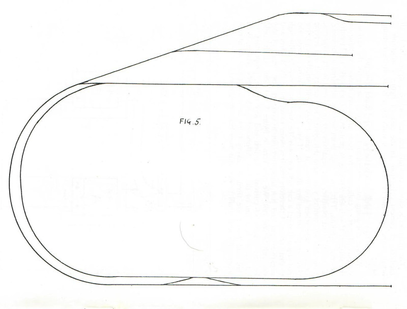
We now turn to Figure 5, a layout which could be any system of current collection and any make, proprietary or otherwise. It is run by the straightforward single supply system. Both dad and junior are tired of taking turns at the control, so a new locomotive and small power unit have been purchased.
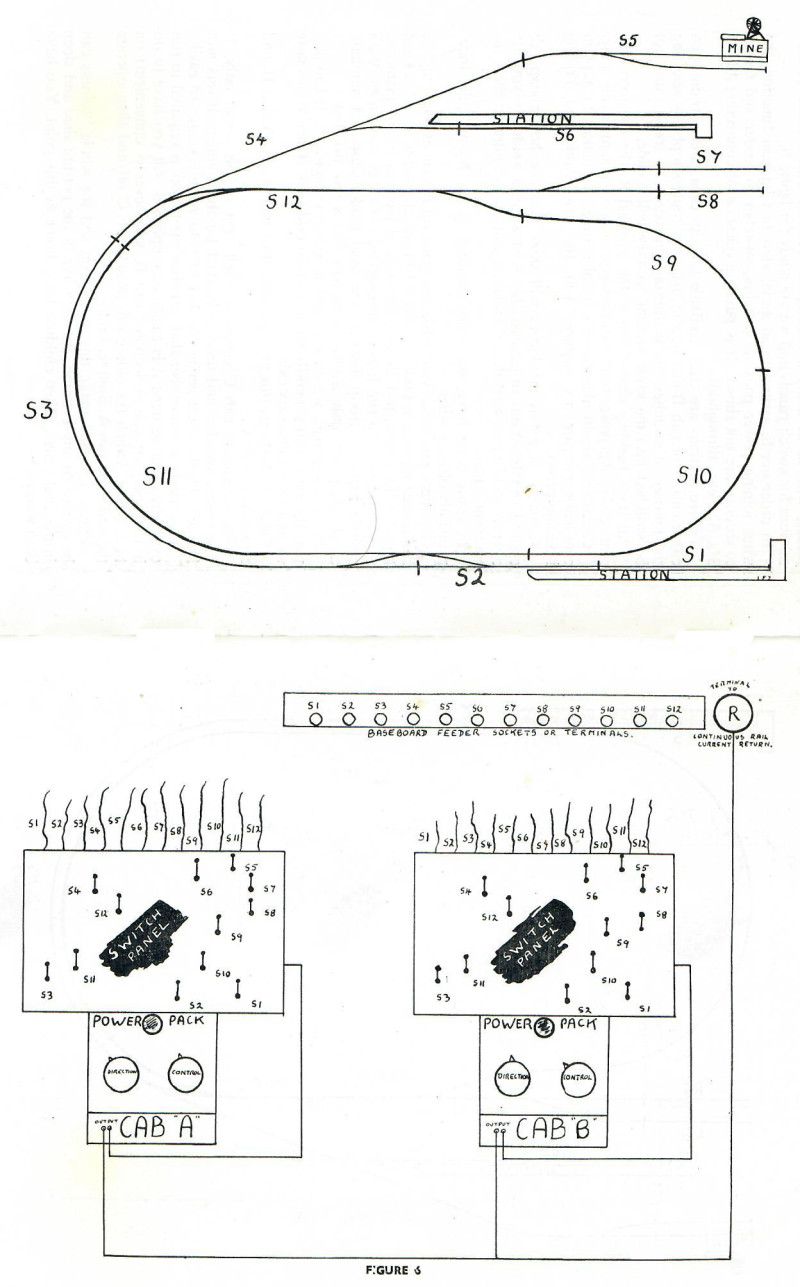
Now we go cab control. A few cuts with a saw, some switches and solder, wire in as many colourings as possible and a sheet of aluminium for switch panels and we are ready for Figure 6. In order not to assimilate an aerial view of Clapham Junction, the wires joining power pack to switches, switches to feeder and feeder to sections are not shown. It is purely a question of connecting all the S1s, S2s, etc., throughout.
Twelve sections are then available to both cabs, and a train from either cab A or cab B can be run over any route simply by selecting the journey in switches. As in railway practice, two trains must not be switched into the same section, as they will collide.
All track bonding should run to the terminal R, the common current return. All power units can be connected to the same mains plug. Crossovers are insulated in the usual manner. Insulators or gaps in conductor rail are not required with the new Dublo and Tri-ang isolating points.
A glance at a few catalogues will show you just how cheap cab control can be. Your original outlay is small and gradually you are able to build up as complex a layout as you may require on the "instalment" plan.
In Figure 6 we have two trains running on our layout quite independently of each other.
Goodness gracious, Aunt Elsie has gone up in our estimation. She has turned up with a tank loco for a Christmas present. It is the right type for the layout, too. Sounds like a good piece of family planning.
Now we want to run it independently of our other two trains. With cash in hand we troop down to the local model shop and purchase a suitable power unit, a little more wire and a few switches.
As it is a tanker, we do not need it to run everywhere. It can service the mine and generally shunt and do odd jobs. Then in this case we employ a subsidiary cab.
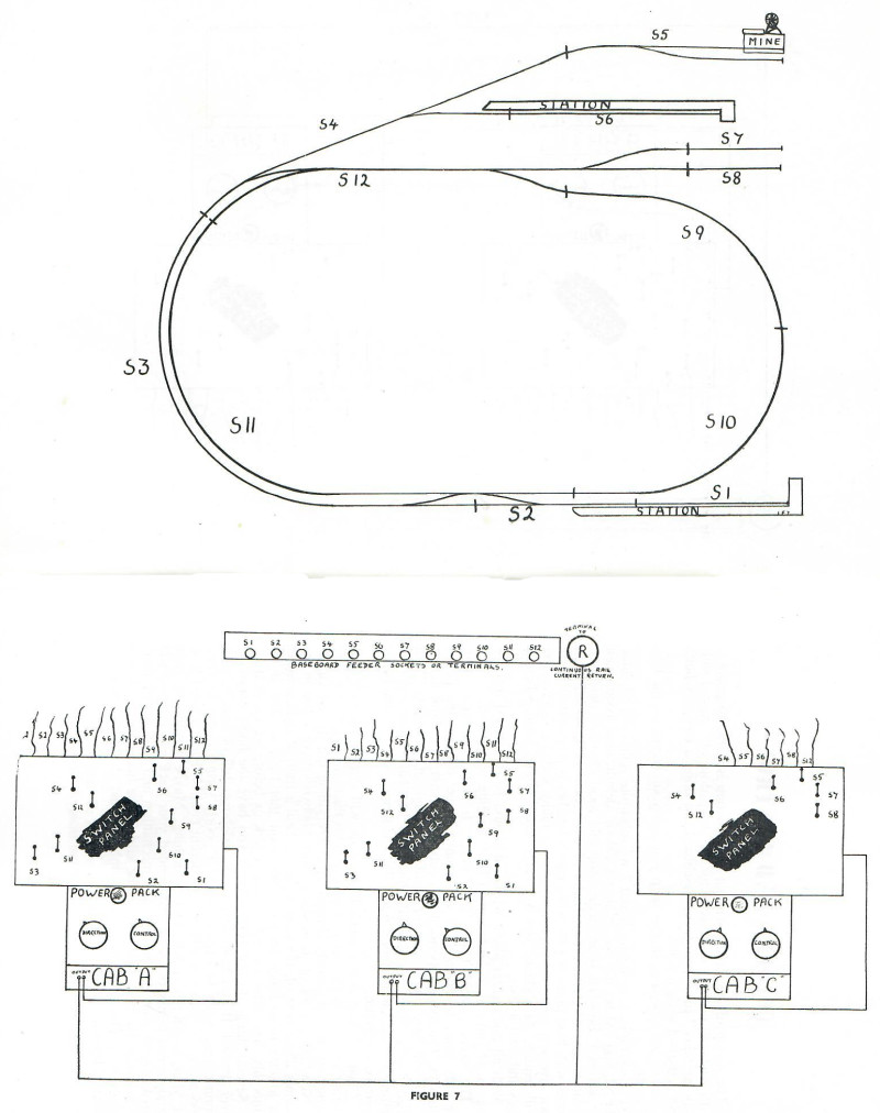
Figure 7 shows us this arrangement - two main cabs, A and B, and a subsidiary cab, C.
The subsidiary cab C covers a small area of the layout only. It saves wire, switches and time. It is ideal for the younger drivers and firemen. They cannot get in the way of your main routings so easily.
It is handy to remember that any time the tanker is required to run over any other sections it is easily accomplished. All you have to do is to park your cab A loco (or cab B, whichever is convenient) on to a siding, switch the siding off, switch cab C off and then operate the tanker on cab A.
Simple, isn't it ?
Figure 7 should make this quite plain and the whole business can be carried to any extreme. We then live in the potting shed and sleep in the coal cellar. Often children leave home at this point. You have been warned!
COLOURS AND CONTROL
The wiring of any layout without some system is liable to prove a trifle puzzling even to its constructor. A sharp dose of "model railway gremlins" just beneath the baseboard can bring a few grey hairs and perhaps a wicked word. Colour identification should keep you and your layout on the best of terms.
For example, if in figures 6 and 7 we substitute yellow for S1, blue for S2, and red for S3, etc., a simple colour identification system can be adopted. Between your model shop and local electrical dealers a great variety of colours and shades of wire could be amassed. Red wires with blue plugs or grey wires with white beads threaded on them can give you enough combinations for as many sections as ever you will require. At a glance you will see where it comes from, where it goes and what it does.
With all this chatter about wiring, it should be mentioned that for the sound running of all layouts a little bonding is required. The return current, that is the "juice" from the continuous rail, or rails, must be given every opportunity to get back to the power supplies. The more opportunities it gets, the keener it is about it. We will have one colour for bonding throughout, say white. "All roads lead to Rome"; well, all white wires lead back to the common return (terminal R in figures 6 and 7). The more you bond, the better your locos will run.
When a layout is not bonded, the train will slow down as it gets farther away from its source of supply. This fluctuating control is very annoying, as it is usually blamed upon everything but its real cause. Now, quite a lot of us model railway hobbyists have a bee in the bonnet about control. We want a loco to haul a train of eight coaches at a scale three miles an hour. We want that train to slow down smoothly, and come to rest without a jerk or before we mean it to. Several things do not help, even if you have the finest controller ever devised. If you have dirty track, axle boxes full of treacle, poor connections, badly laid track, worn or poorly sprung motor brushes, too much oil, then you will not get decent control. Have a good look at your layout; you will find something. Maybe when you have straightened things out a bit and bonded your track as well, you will apologize to your power pack and mechanism and be a happy man. So much has been said and can be said on the maintenance of your equipment. The chief thing to remember is that cleanliness means a healthy layout.
FINER CONTROL
So we are going to be dead fussy. We want to count the spokes on the loco wheels as it creeps along our track.
Provided everything is sound and clean as discussed in the previous chapter, we should stand a chance. An ancient mechanism, with toothless gears or egg-shaped bearings, will not do everything, but we can make some improvements. Our new super-sprung, de-luxe, whistling, smoking, clutch-drive, super detail prize-winning loco could do better.
That old junk heap we purchased second-hand and sweated over on the kitchen table could be inveigled into better behaviour in civilized company. It is easy, cheap and you can do it.
The first thing required is a controller (variable resistance) with as large a movement as possible, say 340 degrees, allowing for the off position. With this type of controller you need a separate reversing switch. They are quite cheap, about 3s. 6d., and work forward/off/reverse.
A very important point to remember when choosing a controller is that the loco should start to move within 45 degrees of throw of the controller knob. The reason for this will soon become apparent. If your loco stops at a resistance of 70 ohms and your controller has a resistance Of 140 ohms, then the loco in question does not move until you are at the half-way mark on the controller. Therefore, on a 340 degree controller, control is available over only 170 degrees. Waste of time, isn't it?
Most commercial mechanisms today in OO or O gauge require nothing over 80 ohms to stop them. A 90 ohm resistance should keep you quite in control with the maximum throw possible.
The makers or suppliers of your locomotives will no doubt inform you of the resistance in ohms required to stop and control them.
For those who prefer a reversing controller (that is a control with one lever covering a forward resistance, an off position and a reverse running resistance) make sure it has the maximum amount of travel in either direction. The longer the throw, the more gradual the control.
The controller for the job has been decided upon. A transformer or transformer/ rectifier (according to the current required for the locos in question) will be needed as well. An automatic cut-out or fuse should be arranged in the circuit to protect the equipment against overloading. A bulb of suitable voltage should be placed in circuit in order that everything is not left switched on when we go to bed.
Most commercially produced units are already fitted with overloads, fuses, or both; some have pilot lights. If any one is not fitted, then the expense of fitting the feature absent will be well worth while.
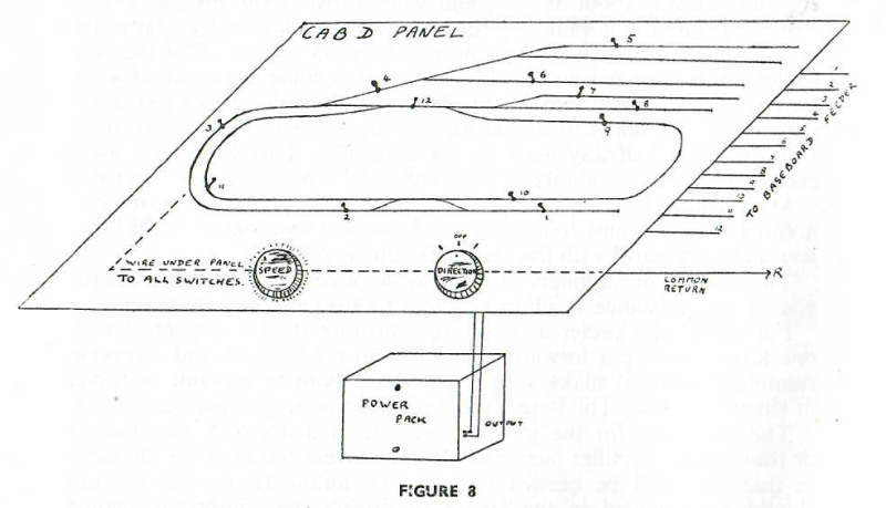
Figure 8 shows a typical set-up with controller, direction switch and transformer/rectifier/power pack. As shown, the transformer/rectifier can be placed anywhere. The whole unit can, of course, be built in together, as you may prefer. The track layout is painted on the panel and the section switches are placed in their appropriate positions.
Wiring to the layout is the same as before, when complete power units were in use. This built-up type cab can be mixed with the complete power-unit type on the same layout. It could control a fourth locomotive and be called cab D.
A complete power pack can, of course, be connected to finer control by turning its control to maximum forward and then running through a 340 degree speed controller.
Any amount of combinations can be used. For example: cab 1, a Formo transformer/ rectifier/controller; cab 2, a Hornby Dublo transformer with Hornby rectifier/controller; cab 3, a Kirdon Midgi-Pak with a VR2 controller. Note that all have a maximum output of 12 volts D.C. at 1 amp. and all would be suitable for a large range of OO and HO locos and mechanisms.
One point that should be brought home at this stage is that a heavily made locomotive has greater adhesion to the running rails. This makes for fine control. Lead can be added to most models and it is amazing what a matter of three or four ounces will do.
NOTE. - If the power pack is not fitted with pilot and cut-out, a bulb of suitable voltage and an auto cut-out should be included in the circuit. It is preferable for a beginner to obtain a power pack with cut-out and/or pilot fitted.
PROGRESSIVE CAB CONTROL
By now, I really hope you understand what is meant by cab control and how to operate your layout by this system.
A mental picture of two operators with two cabs each, driving on signals and to a time-table even, may be leading you into a future of cheaper and better model railways and control.
You may have decided already that your section switches will be double-pole, single throw, so that a light on your control panel tells you where the power is going or available, and whether it is there at all.
Another scheme is worth while giving some thought to for better cab control. What about having a contact shoe on one loco that operates a solenoid motor from a contactor at the side of the track as it travels along? The solenoid will switch the current on to the next section ahead. Another solenoid could switch the current off to the section just cleared. The solenoids could operate signals, too.
Gosh! Just think, the main line express can switch itself through whatever route we drive it from the controller, operating signals automatically.
Various combinations of shoes and contactors could be arranged for a series of trains. Loco contact shoes switch the section on, brake van shoes switch the last section off.
Running by these methods would be even more railwaylike. Your feeling of being in the cab, driving, would be stronger. You would still have to watch signals, and it could not operate without your driving in the most railwaylike manner.
With multiple supply cab control a separate transformer should be used for lighting effects, solenoids and signals. Many automatic features may be incorporated via switch relay and solenoid systems, but it is best not to sap power from a cab supply.
I sincerely hope that you have found your layout has more possibilities than you dreamed of, and that they are all well within your pocket.